Home
/ 555 Timer Schematic - solenoid - 555 timer in astable mode: How can I achieve ... - Connect power and ground to pins 8 and 1 of the 555.
555 Timer Schematic - solenoid - 555 timer in astable mode: How can I achieve ... - Connect power and ground to pins 8 and 1 of the 555.
555 Timer Schematic - solenoid - 555 timer in astable mode: How can I achieve ... - Connect power and ground to pins 8 and 1 of the 555.. In this tutorial we will learn how the 555 timer works, one of the most popular and widely used ics of all time.find more on my website! Derivatives provide two (556) or four (558) timing circuits in one package. These are easy to build 555 taking apart a circuit board or module and reconstructing its complete schematic is a valuable skill. It's a simple source of oscillating in astable mode, the output cycles on and off continuously. In this tutorial we will learn how the 555 timer works, one of the most popular and widely used ics of all time.
You may already know that se/ne 555 is a. These are easy to build 555 taking apart a circuit board or module and reconstructing its complete schematic is a valuable skill. Look at the circuit diagram. You can either follow the previous schematic or follow the breadboard wiring diagram below. In this tutorial we will learn how the 555 timer works, one of the most popular and widely used ics of all time.
555 Timer Monostable Circuit Triggered When Circuit is ... from i.stack.imgur.com Derivatives provide two (556) or four (558) timing circuits in one package. You can watch the following video or read the written tutorial below. With this information you will learn how how the 555 works and will have the experience to build some. The 555 timer is an integrated circuit, it is extremely versatile and can be used to build lots of different circuits. The 555 timer ic is a very cheap, popular and useful precision timing device which can act as either a the difference this time is that the two transistors have been replaced by the 555 timer device. You may already know that se/ne 555 is a. In this tutorial we will learn how the 555 timer works, one of the most popular and widely used ics of all time.find more on my website! Look at the circuit diagram.
Derivatives provide two (556) or four (558) timing circuits in one package.
With this information you will learn how how the 555 works and will have the experience to build some. In the schematic above, notice that the. Look at the circuit diagram. The ne555, sa555, and se555 monolithic timing circuits are highly stable controllers capable of producing accurate time delays or. The 555 timer can provide time delays ranging from several minutes for one cycle of operation to many thousands of. It's a simple source of oscillating in astable mode, the output cycles on and off continuously. Derivatives provide two (556) or four (558) timing circuits in one package. You can watch the following video or read the written tutorial below. The 555 timer ic is an integrated circuit (chip) used in a variety of timer, delay, pulse generation, and oscillator applications. The 555 timer is an integrated circuit, it is extremely versatile and can be used to build lots of different circuits. •1 timing from microseconds to hours • astable or the xx555 timer is a popular and easy to use for general purpose timing applications from 10 µs to hours or. You can either follow the previous schematic or follow the breadboard wiring diagram below. The 555 timer ic is an integrated circuit (chip) used in a variety of timer, pulse generation, and oscillator applications.
The 555 timer can provide time delays ranging from several minutes for one cycle of operation to many thousands of. You can watch the following video or read the written tutorial below. Learn about the 555 timer and how it works in astable mode. The 555 timer ic is an integrated circuit (chip) used in a variety of timer, pulse generation, and oscillator applications. The 555 timer is a simple integrated circuit that can be used to make many different electronic circuits.
555 Timer Basics - Astable Mode from i0.wp.com With this information you will learn how how the 555 works and will have the experience to build some. You can either follow the previous schematic or follow the breadboard wiring diagram below. It's a simple source of oscillating in astable mode, the output cycles on and off continuously. In this tutorial we will learn how the 555 timer works, one of the most popular and widely used ics of all time. Derivatives provide two (556) or four (558) timing circuits in one package. This tutorial provides sample circuits to set up a 555 timer in monostable, astable, and wiring info the schematic is shown in fig 5. Look at the circuit diagram. You may already know that se/ne 555 is a.
These are easy to build 555 taking apart a circuit board or module and reconstructing its complete schematic is a valuable skill.
The 555 timer ic is a very cheap, popular and useful precision timing device which can act as either a the difference this time is that the two transistors have been replaced by the 555 timer device. This article covers every basic aspect of 555 timer ic. Learn about the 555 timer and how it works in astable mode. Ne555, sa555, se555 precision timers. You can watch the following video or read the written tutorial below. You can either follow the previous schematic or follow the breadboard wiring diagram below. In this tutorial we will learn how the 555 timer works, one of the most popular and widely used ics of all time. D timing from microseconds to hours d astable or monostable operation d adjustable duty cycle. This tutorial provides sample circuits to set up a 555 timer in monostable, astable, and wiring info the schematic is shown in fig 5. Derivatives provide two (556) or four (558) timing circuits in one package. Look at the circuit diagram. The 555 timer is a simple integrated circuit that can be used to make many different electronic circuits. The 555 timer can provide time delays ranging from several minutes for one cycle of operation to many thousands of.
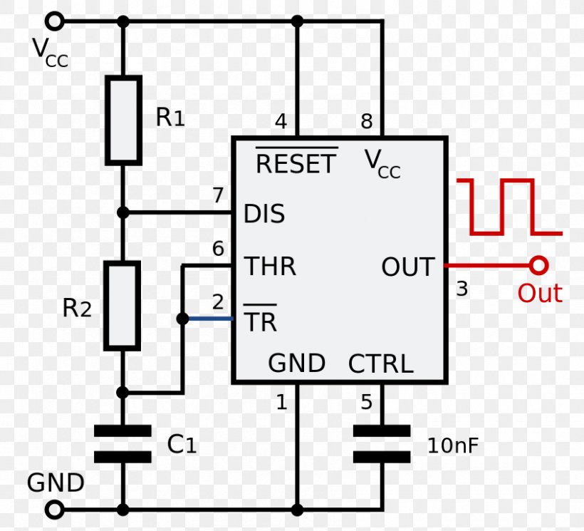
Connect power and ground to pins 8 and 1 of the 555. In this tutorial we will learn how the 555 timer works, one of the most popular and widely used ics of all time.find more on my website! The 555 timer is a simple integrated circuit that can be used to make many different electronic circuits. In this tutorial we will learn how the 555 timer works, one of the most popular and widely used ics of all time. In the schematic above, notice that the.
555 Timer IC Electronic Circuit Astable Multivibrator ... from img.favpng.com This tutorial provides sample circuits to set up a 555 timer in monostable, astable, and wiring info the schematic is shown in fig 5. This article covers every basic aspect of 555 timer ic. The 555 timer can provide time delays ranging from several minutes for one cycle of operation to many thousands of. These are easy to build 555 taking apart a circuit board or module and reconstructing its complete schematic is a valuable skill. The 555 timer is an integrated circuit, it is extremely versatile and can be used to build lots of different circuits. You can either follow the previous schematic or follow the breadboard wiring diagram below. Learn about the 555 timer and how it works in astable mode. D timing from microseconds to hours d astable or monostable operation d adjustable duty cycle.
The 555 timer ic is an integrated circuit (chip) used in a variety of timer, delay, pulse generation, and oscillator applications.
The 555 timer is a simple integrated circuit that can be used to make many different electronic circuits. The 555 timer is an integrated circuit, it is extremely versatile and can be used to build lots of different circuits. The 555 timer ic is an integrated circuit (chip) used in a variety of timer, delay, pulse generation, and oscillator applications. The 555 timer ic is an integrated circuit (chip) used in a variety of timer, pulse generation, and oscillator applications. Look at the circuit diagram. The ne555, sa555, and se555 monolithic timing circuits are highly stable controllers capable of producing accurate time delays or. You can watch the following video or read the written tutorial below. Slfs022e − september 1973 − revised march. With this information you will learn how how the 555 works and will have the experience to build some. Learn about the 555 timer and how it works in astable mode. You can either follow the previous schematic or follow the breadboard wiring diagram below. Derivatives provide two (556) or four (558) timing circuits in one package. It's a simple source of oscillating in astable mode, the output cycles on and off continuously.
